|
P R A N C I N G M O O S
E . C O M D A V E ' S V O L V O P A G E
|
||||||||||||||||||||||||||||||||||||||||||||||||||


 alternators are known for poor voltage.")


| https://www.youtube.com/watch?v=XZM7n9MXciQ |
| Questions? CONTACT
ME Update September 2024: MS harnesses and parts are now out of stock - no longer available. |
|
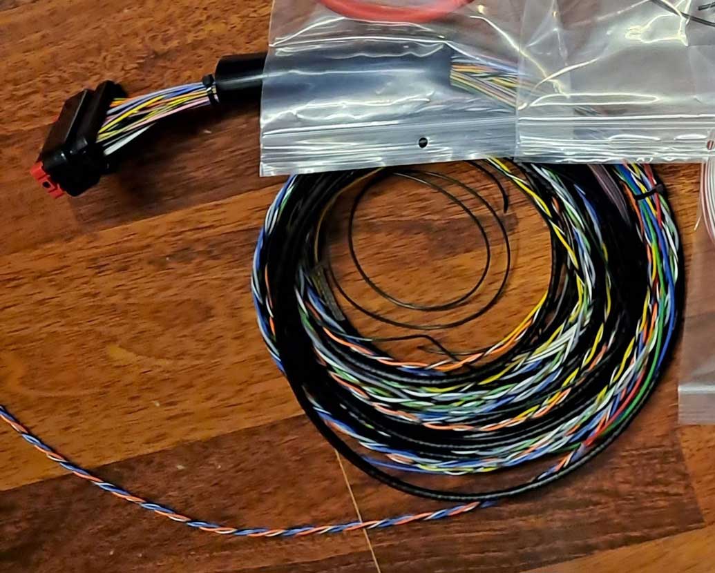

These harnesses are no longer being made, however this information will remain here for anyone wishing to use it to create their own harness builds. The harness PDF assembly guide linked below has been enhanced and offers extensive detail for anyone wishing to use it for your own harness build project. All parts, connectors and terminals are fully detailed with dimensions, sizes and part numbers, etc. needed to complete a harness build on your own.  CLICK IMAGE FOR LARGER ONE 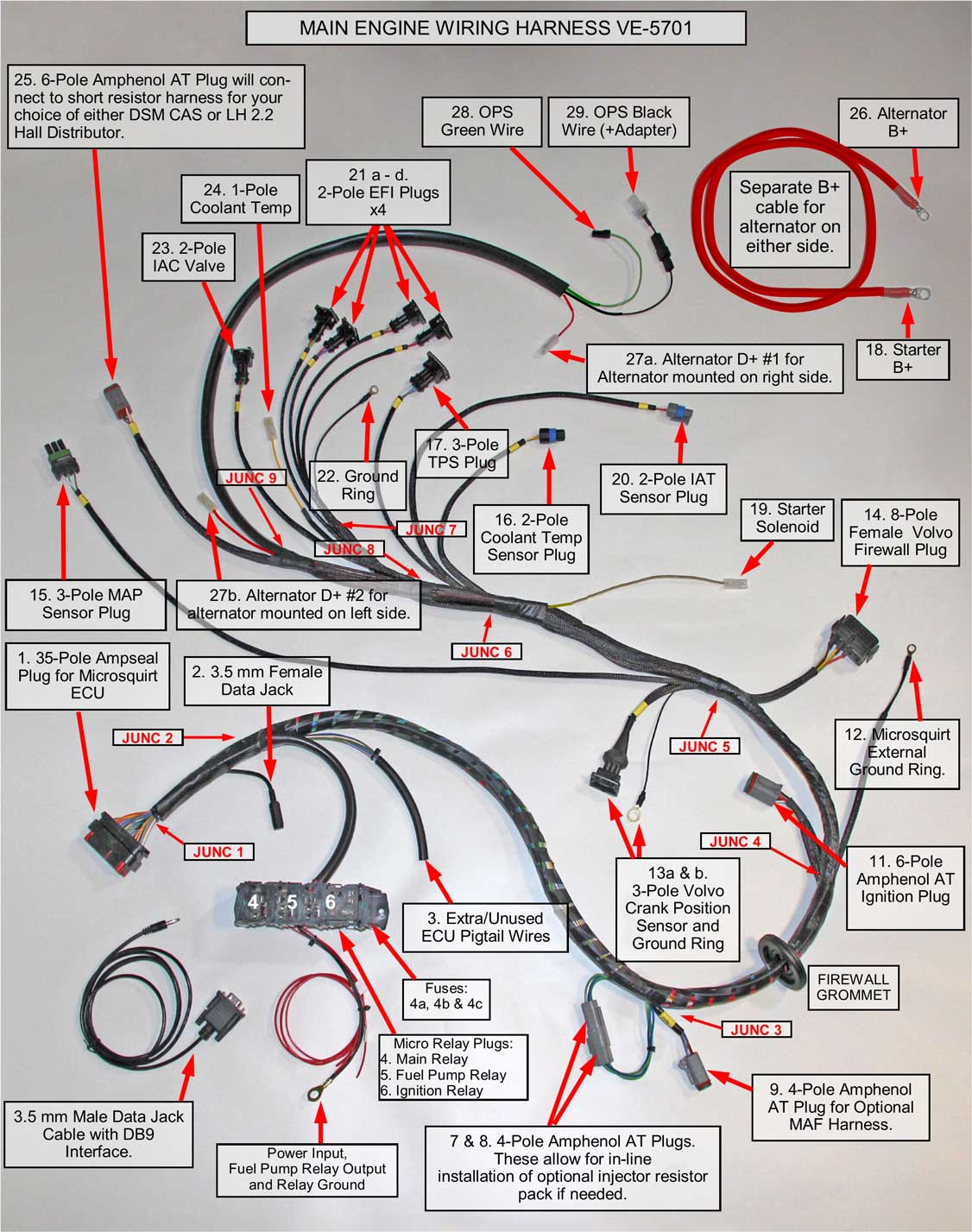 FULL 240 MS HARNESS GUIDE (41 pages, 8 mb PDF) https://www.davebarton.com/pdf/Harness_Microsquirt240-2024.pdf 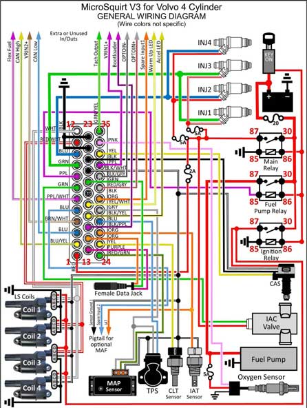
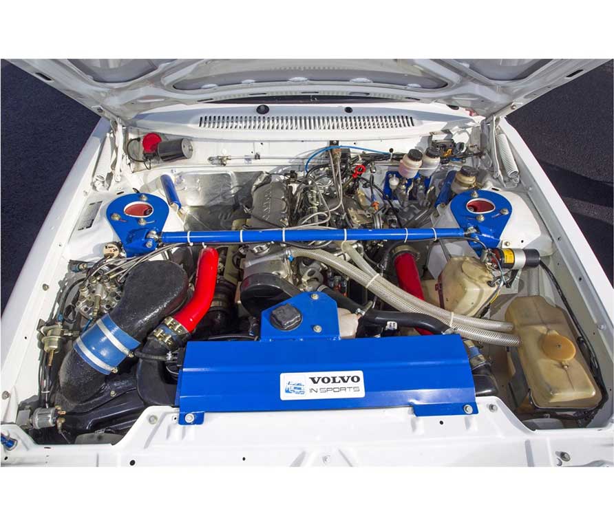
SHIELDING Microsquirt is particularly sensitive to EMI (electromechanical interference). This harness uses noise suppression techniques to reduce interference. One method is to use SHIELDING on sensitive sensor signal wires. If you don't understand how shielding works, here's a short video. https://youtube.com/shorts/chbmHJWtE-0?si=5e0PH73N2B_2r3TC 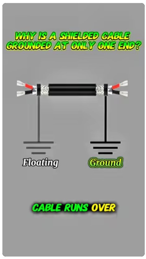  FULL DESCRIPTION Microsquirt V3 engine harness for Volvo 240 (or 740) 4 Cylinder (Microsquirt ECU not included) This main engine harness has been specifically designed for the use of Microsquirt V3 with a Volvo 4 cylinder in a 240. The 740 version harness may be found HERE.
RELAY AND FUSE BLOCK 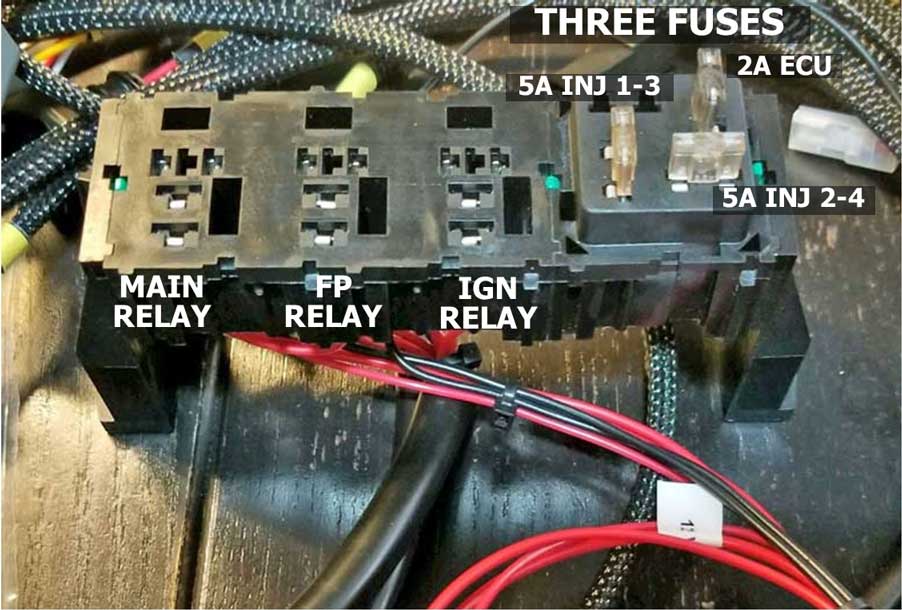 |
|
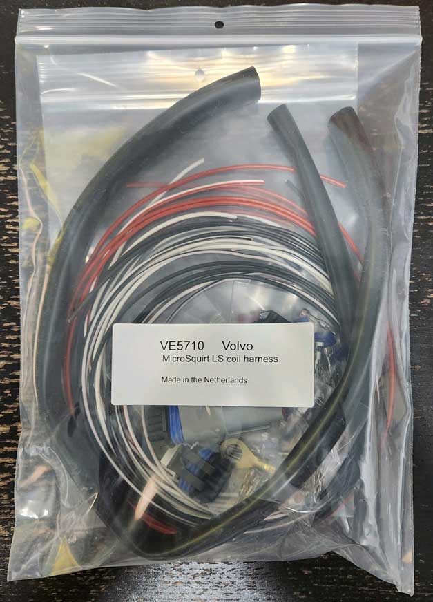
CLICK IMAGE FOR LARGER ONE 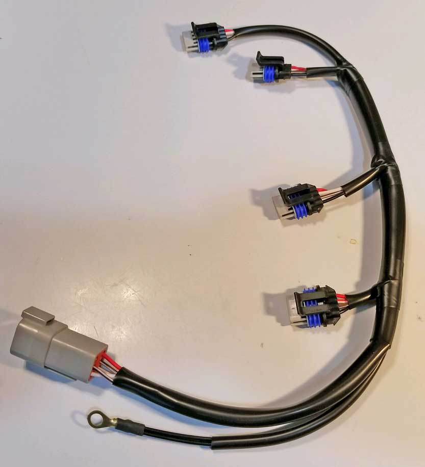 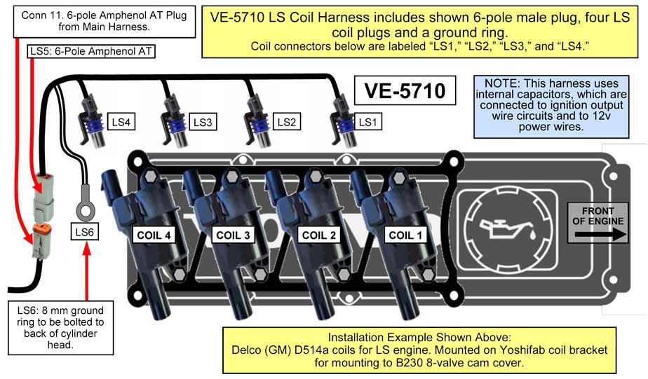 This optional sub-harness is designed to use four GM LS style coils. LS coils have built-in igniters and may receive logic level signals directly from the two Microsquirt ignition outputs. No external ignition amplifier is needed when using this coil configuration. Many ignition modules (AKA "igniters") and some coils with built-in igniters (such as the LS coils) require a logic level signal for operation. Generally this means a 0 or 5 volt alternating signal is received at the coil signal pin. This 0 or 5 volt signal alternates at appropriate times to activate DWELL and SPARK. Most logic level coils, including an LS coil, work in a positive logic mode. When 5v is received to the coil signal pin, the coil begins to charge (DWELL). Then when the signal alternates to 0 volts, the coil fires (SPARK). WASTED SPARK EXPLANATION The FIRING ORDER for a 4 cylinder engine is 1-3-4-2. With this harness option you may use four logic level Delco (GM) D514a coils, which are wired to TWO Microsquirt ignition outputs. These are configured to fire in sequence, which means: COIL 1, then COIL 3, then COIL 4, then COIL 2. To accomplish this using only TWO ignition outputs, the outputs will alternate as follows: First IGN OUTPUT1 fires COIL 1 and 4. Then IGN OUTPUT2 fires COIL 2 and 3. Then IGN OUTPUT1 fires COIL 1 and 4. Then IGN OUTPUT2 fires COIL 2 and 3. This accomplishes the proper 1-3-4-2 firing order using this WASTED SPARK configuration. |
CLICK IMAGE FOR LARGER ONE 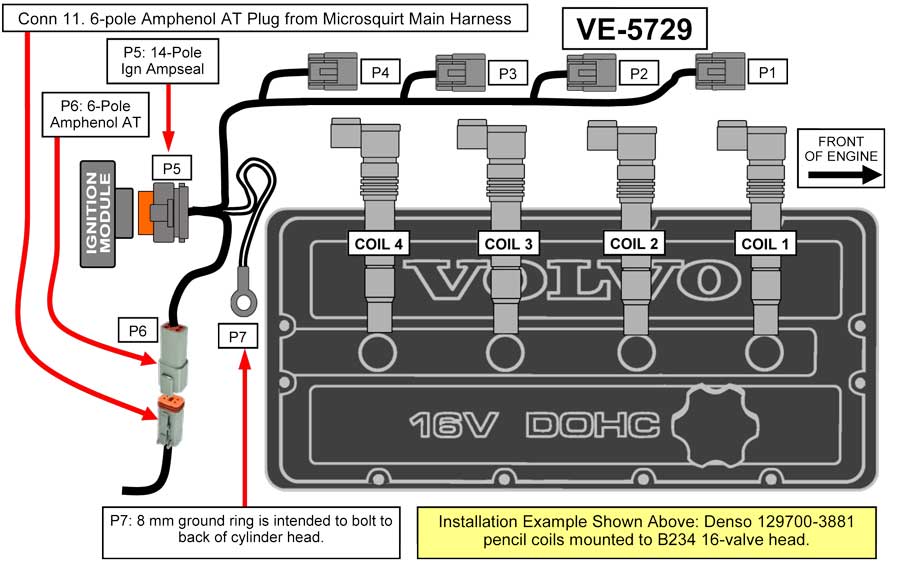 The optional COP Harness comes fully assembled and includes a 6-pole plug, which connects to the main engine harness, a 14-pole plug for the ignition module, four coil plugs and a ground ring. This harness is designed for use with Denso pencil style coils (PN 129700-3881). This sub-harness is intended for use with the YOSHIFAB FOUR-CHANNEL IGNITION MODULE, which may be mounted on the firewall. |
CLICK IMAGE FOR LARGER ONE  This optional sub-harness may be used when a Volvo LH 2.2 style distributor (with internal Hall sensor) is to be used. This distributor will supply the engine timing/speed signal to Microsquirt. Also this sub-harness may optionally be used when an LH 2.4 style crank position sensor (CPS) is used for the engine speed signal. This sub-harness connects the main harness (Conn. 11, 6-pole plug) to the above Bosch single stage ignition module (PN 0 227 100 124), which can be sourced from any LH 2.4 Volvo 240 or LH 2.2 or 2.4 740. |
CLICK IMAGE FOR LARGER ONE 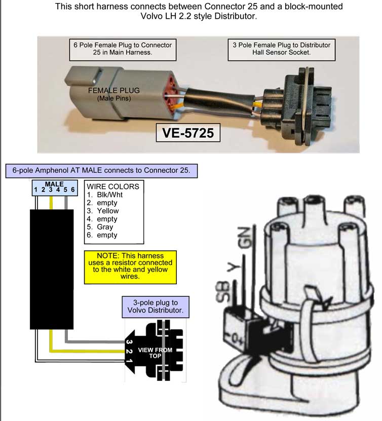 If this is for a 240, this optional sub-harness is intended for use with a Volvo 240 LH 2.2 block-mounted ignition distributor (with internal Hall sensor). This is a standard ignition distributor from an LH 2.2 240, which can be directly plugged into the main harness (using this small adapter sub-harness). If this is for a 740, this sub-harness will also plug into a head-mounted Volvo 740 LH 2.2 ignition distributor. The Hall sensor in the distributor provides needed engine timing/speed for Microsquirt. A single factory style coil may be used. With this option, there are multiple choices available for ignition amplification, but the preferred choice is a Bosch ignition module shown above. |
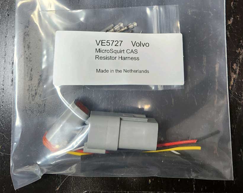
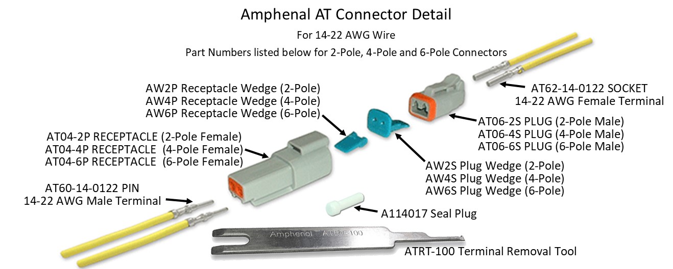
CLICK IMAGE FOR LARGER ONE  This optional sub-harness is intended for use with the Yoshifab Cam Angle Sensor (CAS), which is available for a block-mounted (240) location or for a head-mounted 740 location. The CAS is used to provide engine speed/timing data for the Microsquirt ECU. OPTIONAL 4-POLE CONNECTOR DELETE 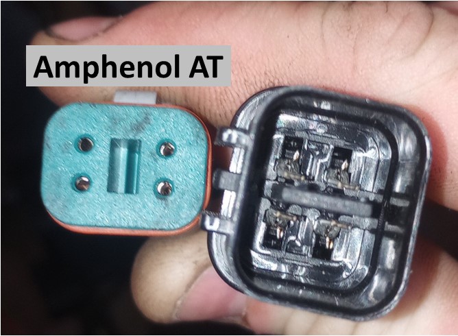 The Amphenol AT 4-pole connector shown above normally comes on this adapter harness and it connects to the Yoshifab CAS. The CAS as supplied by Yoshifab may come with a DIFFERENT connector shown. You may ask Yoshifab to provide the Amphenol AT connector on the CAS, or you may order this adapter harness here without the Amphenol AT 4-pole connector. In this case the harness will come with un-terminated wire pigtails and you can add the connector of your choice. |
[NO IMAGE AVAILABLE] This optional sub-harness is intended for use with an option MAF Sensor. This harness is intended to connect to Connector 9 on the main engine harness. |
HARNESSES NO LONGER AVAILABLE Yes, these harnesses are no longer made, however this information will remain here for anyone wishing to use it to create their own harness builds. The harness PDF guide linked below has been enhanced and offers substantial detail for anyone wishing to use it for your own project. All parts, connectors and terminals are detailed with dimensions, sizes and part numbers needed to complete a harness build on your own. CLICK IMAGE FOR LARGER ONE 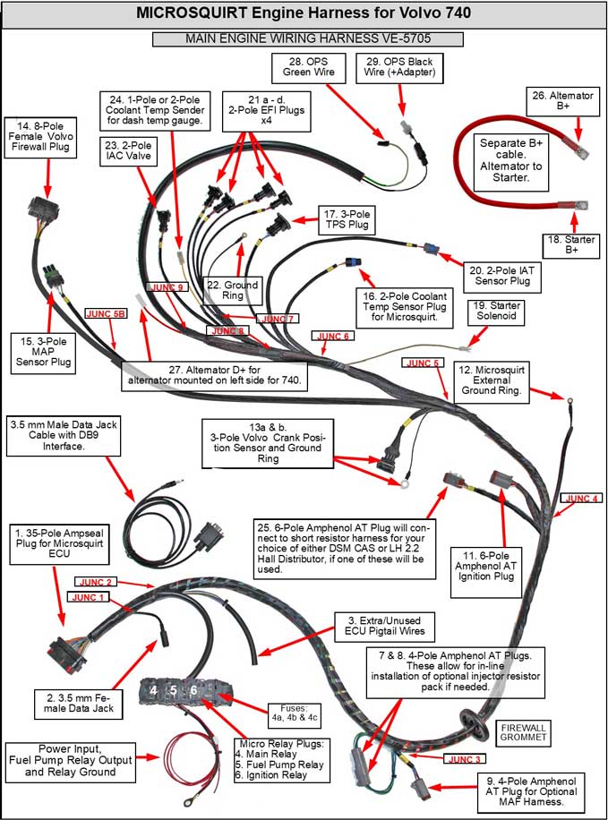 FULL 740 MS HARNESS GUIDE (43 pages, 8 mb PDF) https://www.davebarton.com/pdf/Harness_Microsquirt740-2024.pdf
 |
| OTHER MICROSQUIRT RESOURCES (PDF files) https://www.msextra.com/doc/pdf/Microsquirt_Hardware-3.3.pdf https://www.msextra.com/doc/pdf/Microsquirt_Hardware-3.4.pdf http://www.carquestprofessionals.com/catalogs/engine_controls/Denso-Catalog.pdf https://www.bosch-motorsport.com/content/downloads/Raceparts/Resources/pdf/Data%20Sheet_70101387_Temperature_Sensor_NTC_M12.pdf https://www.finjector.com/documents/51907d67c691b/0280130026.pdf https://m.littelfuse.com/~/media/commercial-vehicle/datasheets/automotive-fuse-holders/powr-blok-modules-datasheet.pdf?la=en https://www.whiteproducts.com/downloads/WhiteProductsCatalog.pdf (Weather Pack) http://www.frankencis.com/portals/FrankenCIS/FrankenCISTechnical.pdf https://www.usshift.com/downloads/tps.pdf http://jimwolftechnology.com/wolfpdf/MAF%20Z32%20CONVERT%20TO%20OTHER%20NISSANS.PDF https://nistune.com/docs/MAF_and_Consult_pinouts.pdf https://www.efisource.com/wp/docs/Microsquirt-stepper-adapter.pdf |
|
|
||||
| davebarton.com |
prancingmoose.com |
240turbo.com |
Special Emblems |
|
| Prancing
Moose Stickers |
Volvo
Stickers |
Body/Chassis/Engine
Labels |
New Items |
|
| Other Car Brand
Stickers |
Steering
Wheel Labels |
Center Cap Labels/Overlays |
Cool Volvo
Products |
|
| Grill Labels/Overlays |
Volvo Wire
Harnesses |
Conversion Harnesses |
Harness
Parts/Connectors |
|
| Volvo Relays |
Coil Repair
Harnesses |
240 Window
Scrapers |
740/940
Window Scrapers |
|
| Adjustable Voltage
Regulators |
Horn Buttons |
240 Odometer
Repair |
740 Odometer
Repair |
|
| Volvo Gauge
Faces |
740
Turbo/Boost Faces |
240 Black Door Vinyl |
850 Odometer
Repair |
|
| ALTERNATOR Page |
240 Power Mirrors - Switches |
240 Oil Cooler Page |
240 Fuse Panel Page |
|
| Group A
Racing 242 Turbo Page |
240 Hydraulic Clutch | Fuel Pump RELAY Page |
240 Headlight RELAY Page |
|
| Used Parts & Extra Stuff for sale |
CRIMPING Page |
240 Ignition Page |
240 Headlight Page |
|
| 240 Gauge Electrical Diagrams | 240 REAR END Page | Yoshifab Catch Can Install | 240 MODS and FIXES Page | |
| Side Marker
Lights Page |
Gentex Mirror Upgrade | Yoshifab Drain Tube Install | Modified 240 Favorites | |
| SoCal Salvage Yards | Unleaded Racing Fuel | B26FT Stroker | Dave's 245 Spec Page | |
| 240 SUSPENSION Page | 240 Lowering Page |
240 Windshield Page |
240 WIPER Page | |
| 240 Big
Brakes Page |
240 Dash Top Gauge Pod | Cadillac 4-Note Horn Install | 240 DYNAMAT Installation | |
| 4 Speed Fan
Controller |
Electric Cooling Fan
Page |
BRUSHLESS Cooling Fan Page |
Tropical Fan
Clutches |
|
| 240 AC Page | "KOMFORT BLINKER" Upgrade | T5 Trans Conversion Page | 240 Engine Mount Page | |
| 240 VIN Page | Stepper Idle Valve Page |
Vacuum Diagrams | 240 HOOD Page | |
| 240 Exhaust Page | 242 Power Vent Window Project |
EFI Volvo Pin Function Diagrams |
Favorite Links | |
| R-Sport
Apparel |
Prancing
Moose Apparel |
Volvo Meet Photo Albums | Texas Volvo Meets and Events | |
| Ordering Instructions | Policies | PAYMENTS Page |
Mojave Road Trail Map Page |
|
| Returns | Shipping | Shopping Cart Troubleshooting | Contact Us |
|
|
|