D A V E ' S V O L V O P A G E
|
||||||||||||||||||||||||||||||||||||||||||||||||||


 alternators are known for poor voltage.")


| For 850 Odometer repair, CLICK HERE. |
| For very EARLY 740-760 Odometer Repair, CLICK HERE. |
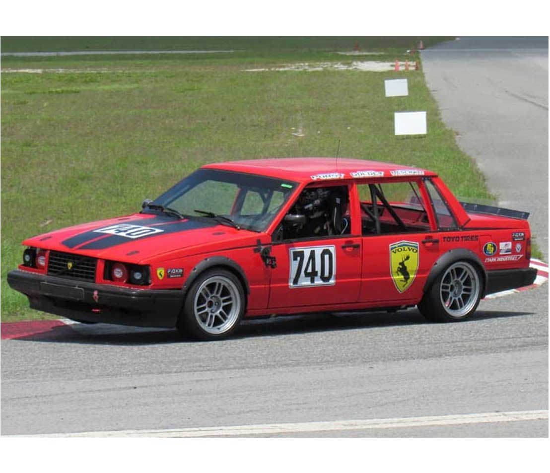
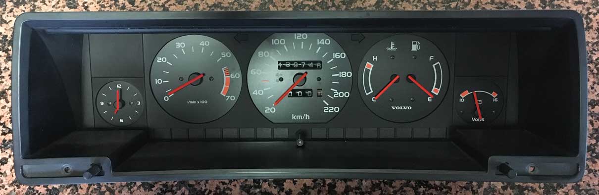
1984-1992
740-760-780
VDO Speedometers |
|
| ORDER MENUS |
Just wanted
to let you know that I sent my cluster for my 1992 740 odometer/trip meter repair, to West Valley Instrument Specialists (Speedometer Plus) at 19314 Vanownen
Street, Reseda, 91335, https://www.westvalleyinstruments.com. They promptly did the repair
and everything seems to be working great. And they have a one year
warranty. I would definitely recommend them. |
For more information on YAZAKI speedometers and instrument clusters, try the below links: http://cleanflametrap.com/speedo7.html https://www.volvoclub.org.uk/faq/ElectricalSpeedometerRepair.htm |
| For a printable PDF
version of these instructions, click here: www.davebarton.com/pdf/700speedorepair2.pdf (1.3 mb) |
| Authorized Dealer
- OdometerGears.com MADE IN U.S.A. CLICK HERE FOR ORDER INFO
|

| Broken odometers in Volvo 740s are getting to be pretty common. Luckily, for most of us, there are now easy fixes for little nuisances like this. The instructions below was written by Bob Griffin, an affiliate of the Volvo Owners Club, United Kingdom. |
A replacement speedometer is not longer available from Volvo and it's getting
more difficult to find a used and fully
functional speedo.
As the speedo needle was working faultlessly I decided to try and find out as much as I could about the speedo unit before I extricated it in an attempt to fix the problem. As the speedo needle was clearly fragile I was worried about its removal without damaging it.
Over the years the design of the VDO speedo has progressed from a cable driven metal cased unit to the newer ‘plastic’ framed electronic versions of the mid-1980s and 90s, as fitted in some 200/700 and 900 Series. The basic design of the speedo remained mostly unchanged, except for the gradual introduction of more electronics. In consequence, similar faults arose across model ranges with VDO instrument clusters. In the case of the VDO electronic odometer, one of its primary faults (there are two commonly known) is the failure of small teeth on a very small plastic gear attached to a small stepper motor inside. This gear is needed to drive the odometer cogs forward. One or two teeth will fail eventually, causing the odometer to cease. What is it they say … “something is only as strong as its weakest link”, and this little insignificant gear is just that. Some say the failure of the gear teeth is attributable to resetting the trip odometer when the car is moving and the odometer turning. This seems logical, but whether or not it is true, or the plastic of the gear wheel just becomes brittle with age, I have no idea. Whatever, I shall not be trying to re-set the odometer whilst the car is moving, but it’s very difficult to break the habit of a lifetime. Before I started, I was lucky to obtain a complete identical VDO cluster (with one exception) from a 1989 745 base model so I had the luxury of not worrying if I "messed up" the original speedo. All I had to do to the replacement (other than trusting the assurance I had been given that everything worked) was to swap it over after swapping two plastic warning light strips at the inside bottom of the cluster for similar strips in my original cluster. The warning light sequence is different between models versions, but the VDO cluster appears to be the same with the same multi-plug connectors, etc. on the back of the cluster. Volvo used different wiring looms with multi-plug connectors wired to suit different model versions, but there is usually no problem as long as you have the right warning light sequence across the bottom of the cluster. Changing those strips was a matter of "plug and play" and everything worked well. In my searches for information I found an article in Dutch on the Nederlands Volvo Forum website, followed shortly thereafter by one on the VOC Forum website. Although the VDO speedo units looked more or less the same, the method of removing the needle was different in each. I was unable to resolve the issue so I had to proceed with care. Several American firms offer replacement gears. After reviewing them I sent an email, together with some photos, to Dave Barton who replied by return. We concluded that there did not seem to be any material difference between what I had ascertained by this time to be my "dead" 25 tooth gear wheel and those Dave had in stock for the 200 Series VDO speedo. In the States I understand that VDO speedos fitted to 740s are likely to have 26 toothed gear wheels. This is not the case with UK models. To date I have not yet heard of one in the UK fitted with anything other than a 25 toothed gear wheel. So, depending upon where you live beware and ensure you get the right replacement. I assume it is something to do with different rear differential ratios between the two markets. Dave Barton’s cost was competitive, and as his help could not be faulted, I ordered and paid for a couple of gears via his secure website. The gear wheel appeared to be a perfect replacement part. In fact it looked better made than the original. All I had to do now was to fit the gear and re-assemble the speedo. The main parts of the odometer fix sequence are illustrated below, together with comment. If you are unsure how to extract the cluster and separate its two component halves that is dealt with briefly at the beginning, but to start with a quick recap on the speedo set-up. The VDO speedo and the odometer are driven off a sensor on the rear differential. The input signal derived from the sensor is fed via the wiring loom (and connectors) to one of the multi-plugs on the back of the cluster where it is linked to the ‘blue’ plastic circuit attached to the white plastic board. From there it is routed via a multi-connector fixed to the white plastic board to the speedo connection by either four contacts on a "wing" (older design), or five metal pins (later design). The "wing" mentioned here can be seen in Pic 2.5 below. The 5-pin connection can be seen in Pic 1.7. The signal then goes via circuitry to an integrated circuit on the circuit board where it is split to drive a galvanometer (the speedo), and a stepper motor that drives the cogs of the odometer. |
|||
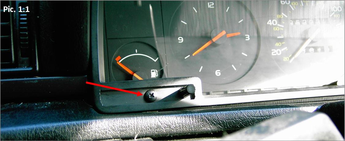
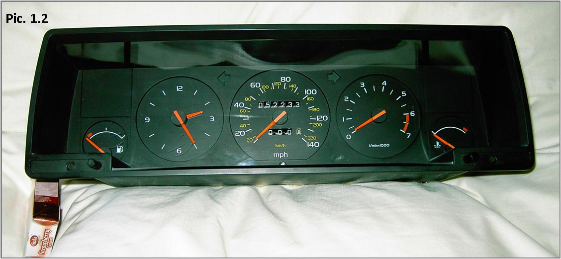
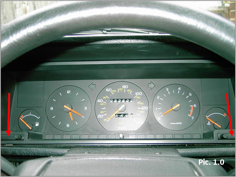 Pics. 1.0 to 1.2: Remove the cluster module from the car. Remove 2 screws at the base of the cluster left and right underneath two plastic "pop-off" blanks adjacent to the rheostat and clock set buttons (indicated by red arrows). |
|||
 |
|||
 |
|||
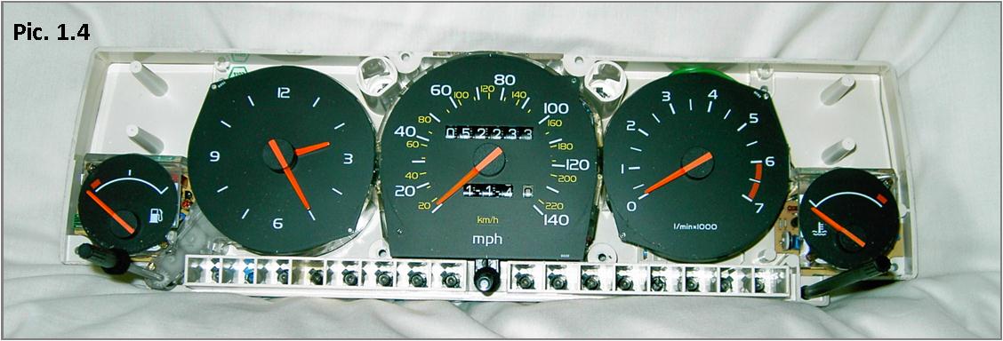
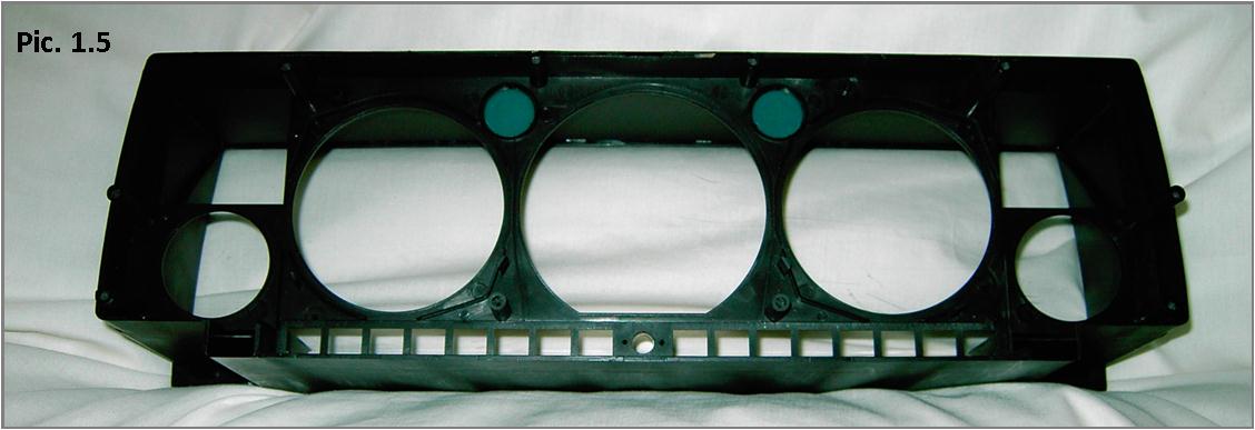
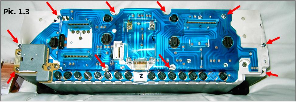 Pics. 1.3 to
1.5: Pics. 1.3 to
1.5:Separate the two halves of the cluster module – remove 10 screws (3 are longer than others) located more or less around the edge of the white plastic backboard. It is only necessary to take out one screw from the lighting rheostat; that at the corner of the white backboard. |
|||
 |
|||
 |
|||
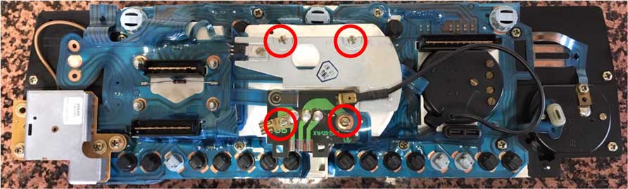
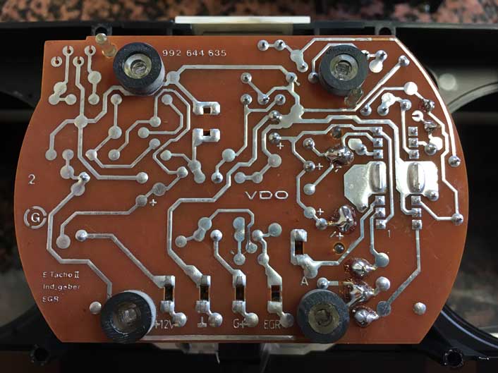
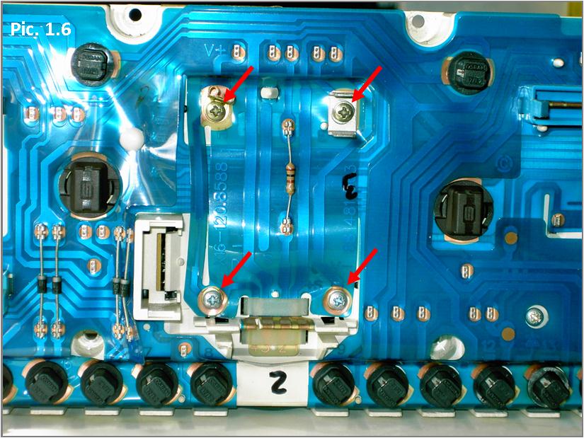 Pic. 1.6: Holding the speedo unit, unscrew it from the white plastic backboard – remove 4 screws (indicated by red arrows). |
|||
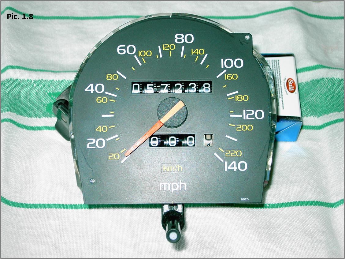
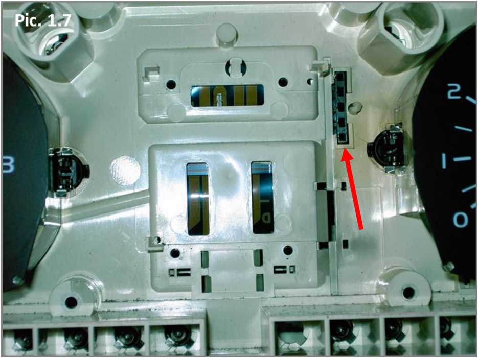 Pic. 1.7 & 1.8: Pic. 1.7 & 1.8:Hold the speedo firmly at the front and pull it straight forward and away from the white plastic backboard. It is a very tight fit between the tachometer and the clock, but with a "wiggle" it will come free and lift off. <<< Take note of the 5-pin connector on this cluster (indicated by red arrow). This cluster is from a later model 740 and you will find references further down in these instructions to a newer 5-pin speedo, as opposed to an earlier speedo without this connector. This 5-pin connector receives the metal pins from the circuit board on the speedometer. |
|||
 |
|||
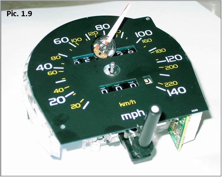 Pic. 1.9: Pic. 1.9:This section will discuss removing the speedo needle. It will be resting at zero, so then when replacing it, it should be at zero. The pointer is delicate, so do not pull directly on it or bend the plastic pointer …. it will snap! <<< In the case of the later 5-pin speedo shown at left, put your fingers around the central hub, and any finger nails you may have the best you can between the underside of the hub and the faceplate. Now merely pull the hub upwards with light finger pressure and it will "pop" off the central spindle. Be gentle. If it does not come off easily, STOP and think again before you break something. It should be noted that this later speedo has a spindle shaft with a spline at its top, which can be seen in this photo. This spline is made of a separate sleeve of "light" metal that is pressed and crimped on to the shaft. With this design it is not necessary to exert any great force on the needle or hub to remove the needle. The Nederland website suggested that you have to remove the black plastic central hub cap shell before the needle can be taken off the spindle splines. Whilst the spindle spline design was identical to my speedo with the five pin PCB design, this was not necessary. Initially I "played" with the advice; even heating the hub with a hair dryer, but gave up as it seemed an impossible task. It was not necessary as suggested in the VOC Forum article to turn the needle anti-clockwise past zero until you feel it break free. This needle will just come upwards and off under gentle pulling finger pressure. With either the later 5-pin speedo shown here or early 4-pin "wing" design circuit board (shown in Pic. 2.5 below) you do not need to be worried about making any marks to help align the needle when reassembling it. As will be seen, that is simplicity itself. |
|||
 Pic. 1.9 (a): Pic. 1.9 (a):Since I originally wrote this article, I have had occasion to repair a friend’s 1986 VDO speedo with the "wing" tag on the circuit board (refer to this photo at left and also Pic. 2.5 below to see the "wing" tag). Whist there are very small variations in design the biggest difference of note is the method of speedo needle attachment, and therefore removal of the speedo needle from the small galvanometer spindle shown at left. Note: In the photo at left this spindle shaft on this earlier gauge is much smaller (with no splines) than the later type in the above photo, which has a fatter splined spindle shaft. The needle hub on this speedo does not simply ‘pop off’ the shaft as the later speedo above, unless a great deal of upward pressure is applied, which it not recommended. The needle hub on this gauge is pressed and glued on. To remove this needle, very carefully turn the center hub of the needle anti-clockwise against the resistance of its inbuilt internal stop position of zero. Turn the hub gently against this resistance until you are certain it is free. You may hear the glue holding the hub on to the spindle begin to crack lightly as you gently turn it very slowly anti-clockwise. Once it seems to be turning freely, you may begin lifting upwards as you turn. Eventually the hub will lift off the shaft and you will be left with the speedo hub separated from the galvanometer spindle, but with the central splined connector remaining in position firmly attached to the centre of the needle hub (see Pic. 1.9a). |
|||
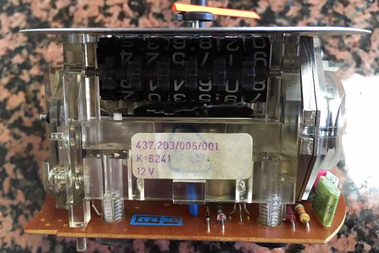
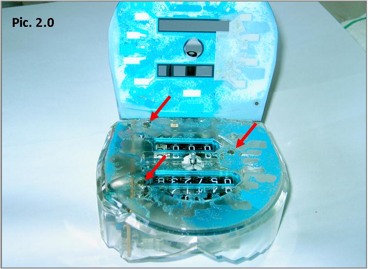 Pics. 2.0 to 2.2: Pics. 2.0 to 2.2:Gently peel back and pull off the dial face. It is "soft" glued to the clear plastic face of the speedo unit. The moulded form of curved clear plastic and "bluing" serves as a light diffuser to illuminate the dial face from the cluster instrument illumination bulbs. Do this very slowly and carefully, and have some cling film ("Glad Wrap") ready to place over the two halves when separated to stop any loose small bits on your work surface getting attached to the glue. Take great care to avoid bending the faceplate; it will slowly peel back and off the front of the speedo and the two small plastic location pegs thereon. In my experience the later 5-pin circuit board design had more soft glue attached to the plastic of the speedo than the earlier "wing" tag version. This made it more difficult to remove the faceplate quickly. Remove the three small brass screws now revealed on the front of the speedo unit (indicated by red arrows). This will separate the speedo unit into two halves; one of which holds all the internal workings of the speedo galvanometer and odometer. |
|||
 |
|||
 |
|||
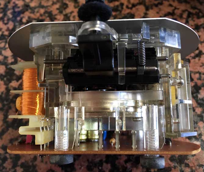
 Pic. 2.3: Pic. 2.3:Now you are free to have your evil way with the errant odometer. Remove the two screws on either side of the stepper motor (indicated by red arrows) and lift the circuit board upwards so that the underside of the stepper motor; the circuit board and gear drive assembly to the odometer are revealed. Let the circuit board "dangle" to one side by the two feed wires. This will reveal two gear wheels at what was the inner base of the stepper motor, together with its rotor; and another gear on the rotor shaft. Don’t worry if the rotor comes free, just put it back into the stator. There is a slight magnetic holding effect. |
|||
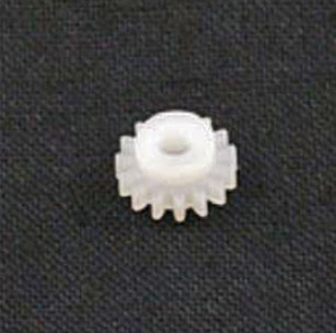
 Pic. 2.4: Pic. 2.4:Here on this later 5-pin circuit board design speedo, the circuit board has been lifted off. Hopefully, after all this you should see that a very small gear wheel (indicated by red arrow) is fitted on a small spindle on one side of a larger gray or white plastic wheel. This larger wheel is known as the "GEAR POD", because it holds the gear. This small gear in this photo has some teeth stripped off. That’s the problem you did all this to fix. You may well see the broken teeth wedged in the stepper motor gear wheel. Should that little gear be intact, look at all the other parts of the gear train for any failure or some physical obstacle preventing the gears from turning. If there are none, it is possible that the problem is electrical and not a bad gear. However, a stripped gear wheel will be the fault in a vast majority of cases, particularly so when the speedo needle works properly or intermittently, but the odometer does not work at all. The most common repair is to replace the small gear with a new one. There are questions about replacing the GEAR POD as well. You should know that it does not usually fail as often as the small gear, but they do also fail. Replacing the small gear only is usually fine, however your POD should be inspected for flaws. Lifting it out, you'll notice there are teeth on the other side that need to be checked. There are professionals who will recommend replacing the gear pod as well, because they feel it will cause trouble later on. The choice is up to you. |
|||
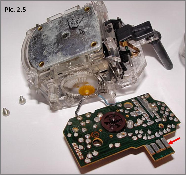 Pic. 2.5: Pic. 2.5:This photo shows an older version of the 740 speedo that has a "wing" off the circuit board with the four electrical contacts on it (indicated by red arrow) rather than the later 5-pin version. If you have the later 5 pin version, you can note that the metal pins on the circuit board will fit through the white plastic backboard into a 5 pin connector, which can be seen in Pic. 1.7 above. |
|||
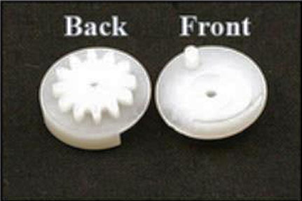
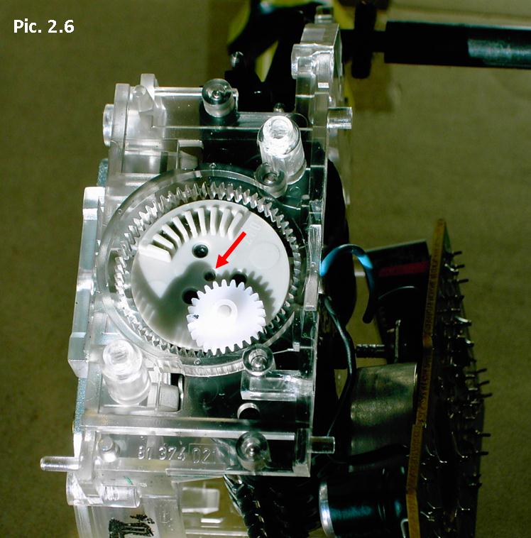 Pic. 2.6 & 2.7: Pic. 2.6 & 2.7:Replace the small gear wheel with an identical new one, paying attention to replace it with the appropriate 25 or 26 tooth gear. In this photo the new small gear on the top of the pod can be seen meshed in its proper position with the clear gear teeth on the outer rim of the speedo case. The rotor of the stepper motor has been removed and is shown above the gears. When assembled properly the rotor fits in the smaller central hole (indicated by red arrow). |
|||
 Before
reassembly
I suggest that you generally clean-up the stepper
motor, including removing the rotor (which merely
pulls out of the stator), and the back of the circuit board,
with a mild solvent, such as Servisol Switch Cleaner,
and wipe it off. If there is an electrical
conductivity problem this could help to resolve it. Before
reassembly
I suggest that you generally clean-up the stepper
motor, including removing the rotor (which merely
pulls out of the stator), and the back of the circuit board,
with a mild solvent, such as Servisol Switch Cleaner,
and wipe it off. If there is an electrical
conductivity problem this could help to resolve it.Closely inspect the top of the circuit board for any capacitors that may have "leaked". This fault is obvious and was a known problem at one stage of manufacture. Continue by checking the underside of the circuit board for any solder joints that might look suspect; the drive gear on the end of the rotor shaft for any faults; as well as the larger gear wheel teeth on the underside of the pod. It is said that this gear can also be problematic. Thoroughly "blow" out the speedo from all angles with compressed air or an air can for, as said, the slightest minute piece of residue from the broken gear wheel teeth or other small bit of whatever can prevent the odometer cogs from turning. |
|||
 Pic.
2.8: Pic.
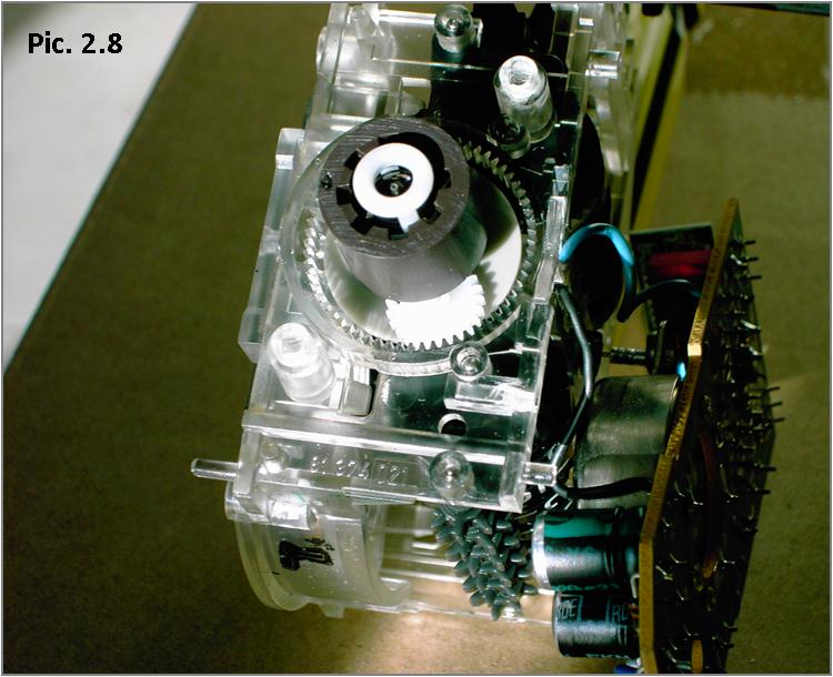
2.8:Before reassembling the stepper motor and screwing down the PCB on to the speedo, align the "pod" and the new gear wheel and inter-meshing gear teeth by inserting the rotor spindle and its attached gear wheel into temporary position, as it should be after reassembly of the PCB. Gently turn the rotor anti-clockwise to check that the odometer gearing and numbers are free and turn smoothly. Re-assembly of the speedo is now the reverse of the removal process. Once the faceplate is back on, refitting the speedo needle is not difficult. In the case of the later 5-pin circuit board version, just push the central needle hub on level and downwards over the splines on the top of the needle spindle so that the needle rests at zero when the spindle mechanism is resting at its natural stop position. The inside of the needle hub does not have corresponding splines, so you don’t have to line up any minute splines to fit the needle on to the splined spindle. It has about four extremely minute raised plastic internal strips in the moulding which, together with the splines on the needle spindle and the close fit ensure the needle remains in place. In the case of the older ‘glued’ needle found on some "winged" circuit boards, you may optionally wipe a minute amount of non-setting glue, or a fixative that will "break free" easily later if needed, on to just one little part of the side of the galvanometer spindle towards the top end (but not on the top) before you push the needle on to the spindle and set it to zero on the internal stop as above. The needle does in any case appear to secure itself to a degree to the spindle without any fixative. If you use glue, make sure you only put only a minute amount on the spindle towards its top. Once assembled there is very little distance between the bottom of the hollow hub shaft and the top bearing of the galvanometer. At all costs you must avoid the slightest excess of any glue "seeping" down the spindle shaft into the top bearing and seizing it as you push the two parts together. I do not recommend the use of super glue (which will run easily), or anything that will permanently fix the needle to the spindle and hub as you may want to take it off again sometime in the future. If the needle is not quite right at first, you may adjust it by turning it slightly to read zero when the spindle mechanism rests at its natural stop point of zero. This is easy to do as long as you remember to hold the hub, not the speedo needle, or it will break. Finally, before and after attaching the speedometer unit to the white plastic backboard and before joining together the two halves of the cluster module and refitting the whole thing to the car; give the needle a couple of small gentle clockwise turns, by twisting it from the hub and letting it go; just to ensure that the needle spring returns the needle to rest spot on at zero. That’s it – hopefully all will be working when you go for a test drive. This Article comes with a warning in that I take no responsibility should you break or damage anything whilst attempting this fix. Just take it easy with the removal of the speedo needle as that’s the most delicate part of the whole operation. |
|||
| Addendum: Very EARLY 740-760 VDO Speedometer/Odometer 1982-83 740 / 760 |
|||
 <<< If you find that you have an EARLY STYLE speedometer in your 740 or 760 you will find different style odometer gears. <<< If you find that you have an EARLY STYLE speedometer in your 740 or 760 you will find different style odometer gears. |
|||
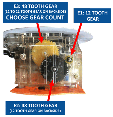 <<<
This EARLY style VDO speedo has very different gears. There are
THREE new gears available to replace these three gears. If you
look closely, you can see that this E1 and E2 gear has damaged teeth. <<<
This EARLY style VDO speedo has very different gears. There are
THREE new gears available to replace these three gears. If you
look closely, you can see that this E1 and E2 gear has damaged teeth.E1: This is always a 12 Tooth Gear. E2: The is always a 48 Tooth Gear with 12 Tooth Gear on Backside. E3: This is a 48 Tooth Gear with a VARIOUS Tooth Count Gear on Backside. NOTE: The E3 Gear is available with 12 to 21 Teeth on Backside Gear. If you need to replace the E3 gear, you will need to count the teeth on the backside of this gear before ordering. These gears are available to order individually or in a set below CLICK HERE. |
|||
 <<< The early style 740-760 instrument cluster will look similar to the later style. <<< The early style 740-760 instrument cluster will look similar to the later style. |
|||
 <<< These four screws need to be removed to access the speedometer. <<< These four screws need to be removed to access the speedometer. |
|||
| HERE ARE SOME VIEWS OF THIS SPEEDOMETER AFTER BEING REMOVED. |
|||
|
|||
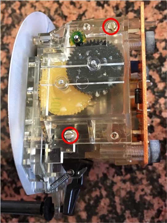 <<< There is NO NEED to remove the speedometer needle or face plate on this gauge. To access the gears, you'll need to remove the two screws shown here. |
|||
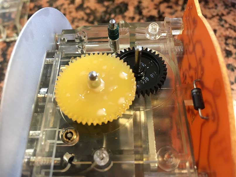 <<< Here's a view after the cover has been lifted off and the E1 and E2 gears removed. The E3 gear (amber colored) remains. |
|||
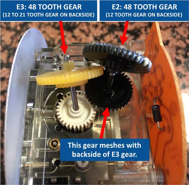 <<<
The E3 gear (amber color) has a gear on the backside that will have
between 12 and 21 teeth. This backside gear needs to be counted
before ordering. If the E3 gear is damaged and you are unable to
count the teeth on the back, you may count the teeth on the small black
gear shown here that it meshes with. This black gear will have the
following teeth corresponding to the E3 backside gear tooth count. <<<
The E3 gear (amber color) has a gear on the backside that will have
between 12 and 21 teeth. This backside gear needs to be counted
before ordering. If the E3 gear is damaged and you are unable to
count the teeth on the back, you may count the teeth on the small black
gear shown here that it meshes with. This black gear will have the
following teeth corresponding to the E3 backside gear tooth count.Small Black Gear: 39 teeth = 21 tooth E3 backside, 41 teeth = 19 tooth E3 backside, 42 teeth = 18 tooth E3 backside, 43 teeth = 17 tooth E3 backside, 44 teeth = 16 tooth E3 backside, 45 teeth = 15 tooth E3 backside, 46 teeth = 14 tooth E3 backside, 47 teeth = 13 tooth E3 backside, 48 teeth = 12 tooth E3 backside. |
|||
|
A few more words of advice:
Look hard for small
broken pieces. Use compressed air
if you have it to help dislodge and remove any
small bits of gear that might be remaining inside.
I received an email from a late model 240 owner who replaced a broken gear and couldn't get things to move more than 1/10 click after several reassemblies. He finally discovered that a piece of the broken gear was lodged in the works. Here's how things went: "It was maddening. I agree, however, 7 times is simply a testament to my stubbornness, or so my wife would say! By the third evolution I could remove the instrument cluster in about 60 seconds and I had the rear wheel jacked up to facilitate a test drive!" "The giveaway was the trip 1/10 numbers would move a bit, then the upper main odometer would look like it was trying to turn, the numbers would move slightly, then it would all stop. It was behaving like a jam was somewhere in there. Your description of not giving up on your mechanical odometer gear troubleshoot was inspirational, I went back and re-read it after the fifth removal." "The broken gear piece was miniscule and the only way I found it was by rotating the gear mechanism with my finger while I had the gear case cracked open. I kept getting to one spot that had noticeable resistance but could see nothing. I ran the tip of a tweezers in between the gear teeth and on one pass a small piece of plastic came out, and that was it." S.D., Wake, VA |
|||
STILL NOT WORKING?
IMPORTANT: READ THIS Please review the "STILL NOT WORKING" section in the 240 odometer page for more clues and suggestions. CLICK HERE |